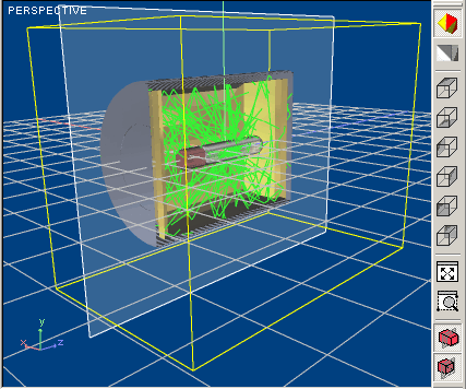
The main part of workspace field is used to display 3D image of Optical System to provide demonstrable and intuitive presentation of it. You can set one of predefined views or set your own point of view, select part of Optical System and get more close view on it or decrease magnifying for survey Optical System as a whole using pointer device. To provide more intuitive understanding of Optical System orientation axes of Global Coordinate System outgoing from their origin is depicted. Those axes are colored differently: Red is Optical System Axis -- 0X, Green is vertical axis -- 0Y, and Blue is horizontal axis -- 0Z. You can also turn on visualization of Horizontal Plane (Z0X) Grid to provide more intuitive representation of Optical System in 3D world. In addition, small image of Global Coordinate System axes is permanently placed at the bottom left part of 3D Layout field with axes colored in the same manner as a major ones to provide understanding of Optical System orientation while you are working with large scale magnification. Name of currently used type of projection you can find at the top left part of the Layout.

With Application, you can analyze energy distribution at any plane parallel to cardinal planes of Coordinate System (namely, X0Y, X0Z, and Y0Z). You can either visualize current position of Analysis plane or hide it at any time you desire. In addition, you can hide part of Optical System situated at positive part of half-subspace (in positive direction of axis normal to Analysis plane).
Toolbar provides access to most general options of Optical System viewing in 3D space. Toolbar is placed at the top right docking area. In addition, you will get access to all options of 3D Layout via either context menu or main menu of Application.
With 3D Layout, you can view also trajectories of rays passed through Optical System.
While any part of Optical System is selected, it will be enclosed in bounding box.
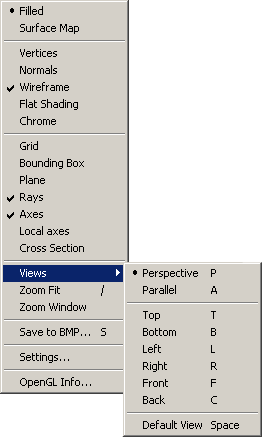
The access to Viewer commands opens from context pop-up menu. In order to call the menu, you should place pointer onto field of layout and press right button of your pointing device.
There is separate toolbar that is associated with 3D Viewer to provide access to the most general options of Viewer. It placed at the left on Viewer layout.
To denote currently selected mode corresponding icon is highlighted as it shown at the table below. Then, icon will be highlighted while pointer is placed over them.
Table below outlines buttons of the 3D Viewer toolbar.
|
|
Set Perspective View projection |
|
|
Set Parallel View projection |
|
|
Show Top View of Optical System |
|
|
Show Bottom View of Optical System |
|
|
Show Left View of Optical System |
|
|
Show Right View of Optical System |
|
|
Show Front View of Optical System |
|
|
Show Back View of Optical System |
|
|
Select part of Optical System and fits selected part inside the 3D Layout window |
|
|
Fits whole Optical System in the 3D Layout window |
|
|
Show or hide Energy distribution analysis plane of Optical System |
|
|
Show cross-section of Optical System |
Context Pop-Up menu becomes available via left button click of your pointing device and provides access to some Viewing and Management options of Optical System. There are three types of Menu points -- Command points to execute corresponding command, Check Box points to select corresponding viewing option, and providing access to pop-up submenu. Menu points unavailable at present time will be grayed.
 |
|
You can either select one of six fixed points of view providing orthogonal viewing of Optical System or change position of viewing point interactively using 3D Orbit feature and panning and rotation options.
Icon corresponding selected viewing option will be highlighted at 3D Viewer toolbar
You can set desired direction of view interactively using 3D Orbit feature.
To set arbitrary viewing direction:
To denote you are currently using 3D Orbit feature
pointer image will be replaced with following one: ![]() .
The current and starting positions of pointer are connected with a line.
.
The current and starting positions of pointer are connected with a line.
You can put desired part of image of Optical System directly before your eyes using panning options. Image follows movement of pointing device.
To pan image:
To denote you are currently using panning mode pointer image will be replaced with following
one: ![]() .
The current and starting positions of pointer are connected with a line. Image follows movement of pointing device.
.
The current and starting positions of pointer are connected with a line. Image follows movement of pointing device.
You can rotate image around axis normal to plane of layout of 3D Viewer.
To rotate image:
To denote you are currently using rotation mode pointer
image will be replaced with following one: ![]() .
The current and starting positions of pointer are connected with a line. Image
follows movement of pointing device.
.
The current and starting positions of pointer are connected with a line. Image
follows movement of pointing device.
Section view is used to provide viewing of internal space of Optical System design. Then, using of Cross-Section view is useful to check Surface Maps of internal Surfaces of System.
To get access to Cross-Section view:
You can visualize position of Cross-Section Plane to get more understandable visualization result.
To turn on visualization of Cross-Section Plane:
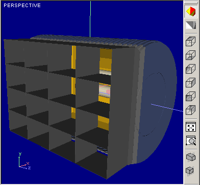
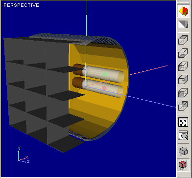
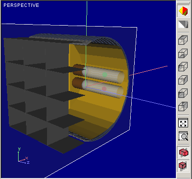
Figures below illustrates affecting
 |
 |
 |
|
View without Cross-Section |
Cross-Section view without Plane visualization | Cross-Section view with Plane visualization |
To set desired position and orientation of Cross-Section Plane, View controls window is used.
To get access to View Control window:
Immediately after it View controls window shown below will appear:

With this window, you are able to set position and orientation of Cross-Section Plane with respect to cardinal axes of absolute Cartesian Coordinate System. All options are realized through control elements placed within Orientation relative to plane and Position frames.
To set desired orientation of Cross-Section Plane:
With option buttons placed at Orientation relative to plane frame, choose desired orientation of Cross-Section Plane. It will be parallel to plane containing axes of Cartesian Coordinate System denoted at right of option button.
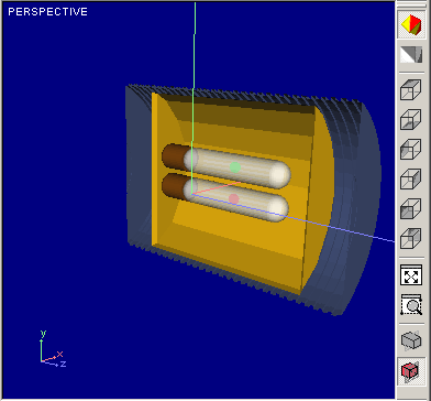
Figures below illustrate affecting of orientation option onto Section View:
 |
 |
|
Cross-Section Plane is parallel to X0Y plane |
Cross-Section Plane is parallel to Y0Z plane |
To change position of visualization plane:
Figures below illustrate affecting of position changing of Analysis plane on visualization result:
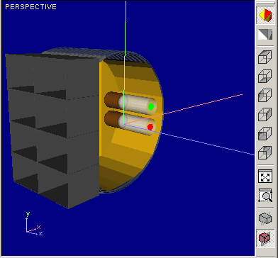 |
 |
| Position Z=0 | Position Z=78 |
You can use your pointing device to set scale of image interactively.
To set image scale interactively:
To denote you are currently using rotation mode pointer
image will be replaced with following one: ![]() .
The current and starting positions of pointer are connected with a line. The
image enlarges and decreases, following mouse moving off and towards user.
.
The current and starting positions of pointer are connected with a line. The
image enlarges and decreases, following mouse moving off and towards user.
In addition, you can fit either whole Optical System or it’s part into window of layout of 3D Viewer anytime you want.
Zoom fit command will not affect any other viewing option like viewing direction or orientation of Optical System.
To fit part of Optical System into 3D Viewer window:
After left button will be released, part of Optical System inscribed into rectangle will be fitted to window of 3D Viewer. Zoom fit command will not affect any other viewing option like viewing direction or orientation of Optical System. Rectangle denoting zoomed part is visible during inscribing procedure. Figure below illustrates process of zooming of part of Optical System.
|
|
|
|
While inscribing |
After zooming |
Zoom window command will not affect any other viewing option like viewing direction or orientation of Optical System.
You can set either Parallel or Perspective projection technique to provide more attractive and intuitively obvious visualization of Optical System. Difference between Perspective and Parallel projection modes is illustrated with figure below:
|
|
|
|
Perspective mode |
Parallel mode |
You can restore default view of your Optical System anytime you want. With this, default axonometric view using perspective projection mode will be restored, and whole system will be fitted into window of 3D Viewer.
There are a number of additional features integrated with 3D Viewer to affect content of Viewer’s Layout. You can visualize structure of 3D model of Elements, show or hide axes of Coordinate System and rays passed through Optical System, set you own color for each Element and use appropriate background scheme and so on. Because of any Element of Optical System can be shown or hidden independently from others you can compose current content of visualization according to your current needs.
To get access to the most additional features of 3D Viewer you can use either context menu or View > 3D Viewer submenu of Main menu. To activate appropriate feature you should simply check corresponding items; being unchecked, feature item is inactive.
Visualization of structure of 3D model of Optical Element is useful to check correctness of Elements of Optical Scheme imported from external CAD applications like AutoCAD or Unigraphics. All options dealing with visualization of structure of 3D model are grouped together. You can use following options:
All options are used in a simple check-in mode. You should check desired option to turn on it; otherwise, to cancel using of any option it should be unchecked.
A number of additional elements can be visualized with 3D Viewer used to provide representation of Optical System and navigation through it in the most obvious manner. All options are grouped together and listed below:
All options are used in a simple check-in mode. You should check desired option to turn on it; otherwise, to cancel using of any option it should be unchecked.
You can set desired background color to emphasize attention to your Optical Scheme. There are two options available for background setting. You can set either solid color for whole background field or two-color gradient fill of background. Both variants are available trough Settings window shown on figure below:
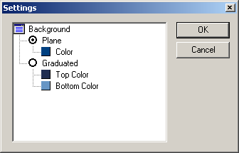
To set desired type of background filling:
To change color of background filling:
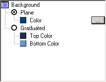
Typical view of Color window is illustrated below:
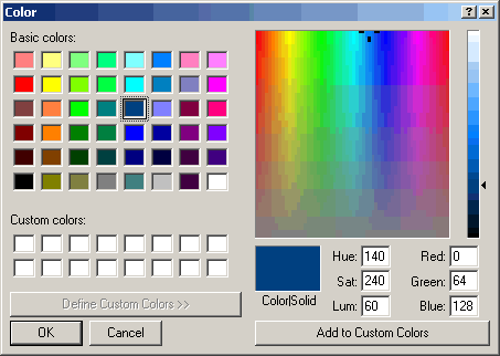
You can set any predefined color from standard palette, set desired color using either HSL or RGB color coordinates, and save up to 16 custom colors for following using.
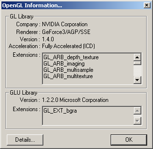
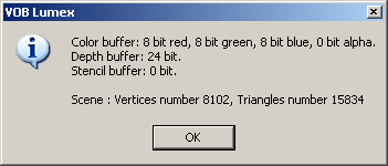
You can get some additional information using context menu of 3D Viewer. It can be realized via OpenGL info command. With it, information about currently used visualization software will be available. In addition, you may get some information dealing with complexity of visualized 3D scene.
To get information about currently used visualization software:
