


|
|
|
For image synthesis built-in test objects like disk (diffraction point), radial
mira or rectangular mira are supplied. Additionally, the user may use images in
standard bitmap format (*.bmp). Image synthesis is done by PSF (point spread
function) for a matrix of points on the object plane. The following samples of
image analysis were generated with a simple doublet system (Fig. 4-1).
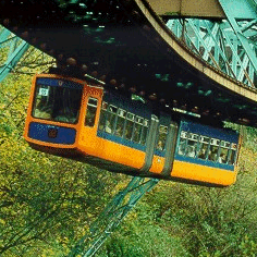
Fig. 4-2a shows a picture of the
"Schwebebahn"
(overhead suspension railway train in Wuppertal, Germany), used as an object.
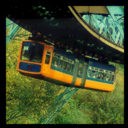
The resulting image (Fig. 4-2) is somewhat blurred due to imperfections of the
lens. It is calculated assuming an ideal detector like a superfine grained
photographic plate.
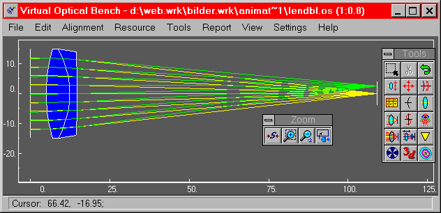
Fig. 4-1: Simple doublet system used for image synthesis examples
|
|
|
Fig. 4-2a: Bitmap used as object for image synthesis
|
Fig. 4-2b: Synthesized image of object in fig 4-2a using doublet system (Fig
4-1)
|
The electro-optical features of detectors can be taken into account. Several
single element, multi-element detectors and mechanical scanners may be used.
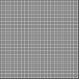
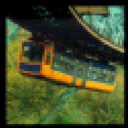
Fig. 4-3a shows a map of a matrix area detector, like a CCD. For demonstration
purposes the dimensions are rather unusual. The resulting image (fig. 4-3b) is
quite pixelized due to the coarse structure of the array.
|
|
|
Fig. 4-3a: Map of matrix detector (3 mm * 3 mm), 50 * 50 elements, element size
0.06 * 0.06, center to center
distance 0.06 * 0.06
|
Fig. 4-3b: Synthesized image (3 mm * 3 mm) with matrix detector (Fig. 4-3a)
|
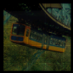
The margins (trenches) between the elements of matrix arrays can be taken into
account. While in fig 4-3 the elements are seamlessly arranged (element size =
center to center distance), in fig 4-4 a more realistic array with margins is
shown. The resulting image is rather dark due to the black margins between the
elements.

|
|
|
Fig. 4-4a: Map of matrix detector (3 mm * 3 mm), 79 * 79 elements, element size
0.03 * 0.03, center to center
distance 0.038 * 0.038
|
Fig. 4-4b: Synthesized image (3 mm * 3 mm) with matrix detector (Fig. 4-4a)
|
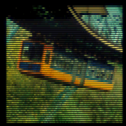
Single and double line arrays (fig. 4.5) are used in fax machines and desktop
scanners for PC`s, which are scanned in one dimension over the images. The
black stripes are caused by the margins of the elements (s. above).
|
|
|
|
Fig. 4-5a: Map of single line detector (3 mm long), 55 elements, element size
0.05 * 0.05, center to
center distance 0.055
|
Fig. 4-5b: Map of double line detector (3 mm long), 2 * 28 elements, element
size 0.05, center to
center distance 0.110 (element to element in one line)
|
Fig. 4-5c: Synthesized image with single line detector (Fig. 4-5a) scanned
horizontally over the image plane
|
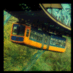
Fig 4-6: Synthesized image with rectangular single element detector (0.08 *
0.08) scanned
horizontally and vertically over the image plane
|
Figure 4-6 shows the image obtained with a rectangular single element detector
which is scanned seamlessly over the image plane. The strong blur is caused by
the rather big element size in relation to the image size.
|
Webmaster`s note:
Soon (ehem, in the next weeks ;-) we will add examples of mechanical scanners
taking into account real movement with relaxation of moving element (mirror).
Please come in again.
More samples?
The trial version of VOB Pro with Micro Optics plug-in contains hundreds of samples covering nearly any application of optical design programs. Use these samples as starting points for own designs.
See the Feature Table for a summary of features supported in each edition.
|
|


