


VOB Virtual Optical Bench Program Series
Optical systems with micro optical elements like lens arrays can be analysed and designed by VOB Pro with the add-on "Micro Optics". The add-on is realized as plug-in and may only be used together with VOB Pro.
Webmaster´s note: We present some first examples of plug-in "Micro Optics" on this page. We will add more information in the next days. Please return to this page. If you would like to get a notice when new informaton is added to our website please send an e-mail with your name, e-mail address and company name (if applicable) to VOBmailing@TECplusplus.de
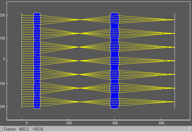
Fig 2-1: 2D image of an optical system with two planar base elements. Each surface is provided with an array of cylindric lenses.
Micro optical structures may be placed on base surfaces of type sphere and plane. The base surfaces may be for example part of lenses, prisms or mirrors. Above a 2D image of an optical system with two planar base elements is displayed (Fig 2-1). Each surface is provided with an array of cylindric lenses.
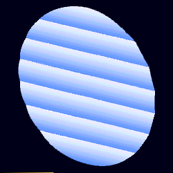
Fig. 2-2: 3D image of a cylindric lens array, structure typical in micro optics |
On the left (Fig. 2-2), a 3D image of a cylindric lens array, as an example of
a structure typical in micro optics. Types of micro surfaces:
|
| The spot diagram (Fig. 2-3) of the optical system in fig. 2-1 shows several stripes, each one a contribution of one cylindric structure. |
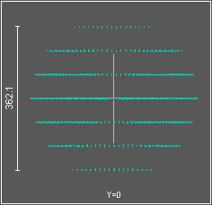
Fig. 2-3 |
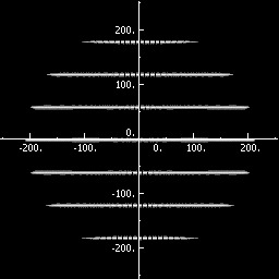
Fig. 2-4 |
The color map of PSF (point spread function) (Fig. 2-4) of the optical system in fig. 2-1 shows several stripes, each one a contribution of one cylindric structure. |
| 3D graph of PSF (point spread function) (Fig. 2-5) of the optical system in fig. 2-1 shows several rectangular bars, each one a contribution of one cylindric structure. |
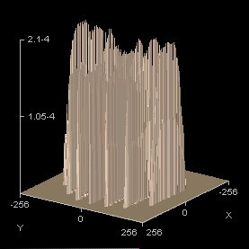
Fig. 2-5 |
